
Steel Structure Erection Marks & Member Marking: How Steel Members Are Identified
A practical guide to steel structure member marking and erection marks: what the marks mean, how members are numbered, marking methods compared, how marking coordinates with packing and container loading, and what buyers should check before shipment.
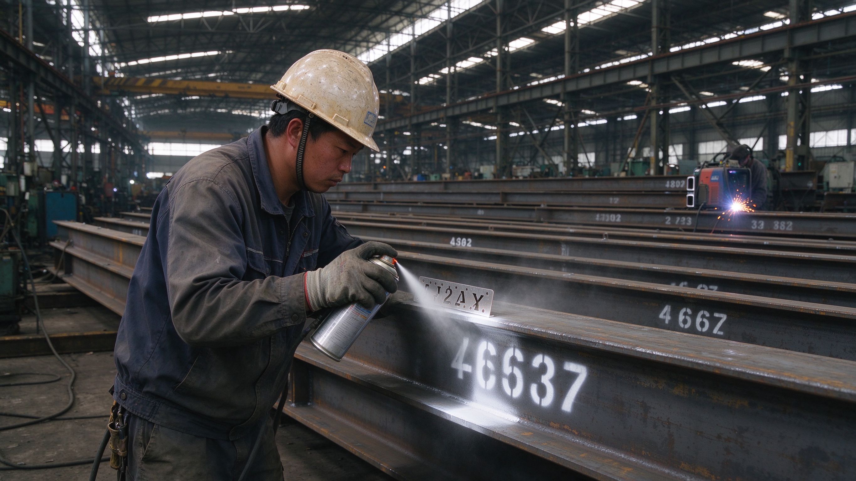
Erection marks are the identification codes painted or fixed onto each steel member so that the site team can find it on the erection drawings and place it in the correct position. A typical mark combines a part identifier (for example a column, beam or purlin code), a sequence number, and sometimes a mirror/side indicator, and it must match the mark shown on the shop drawings and erection drawings. Without a consistent marking system, even a perfectly fabricated structure becomes slow and error-prone to erect: members are searched for by trial, lifted into the wrong position, or re-cut on site. Marking is part of the steel supplier’s fabrication and packing scope, but its usefulness depends on drawings that the local team can read and on a loading sequence that matches the erection sequence.
This guide explains how steel members are numbered, how marking methods compare, how erection drawings and shop drawings differ, how marking ties to packing and container loading, and what buyers should check before shipment.
Part 1: What erection marks are and why they matter
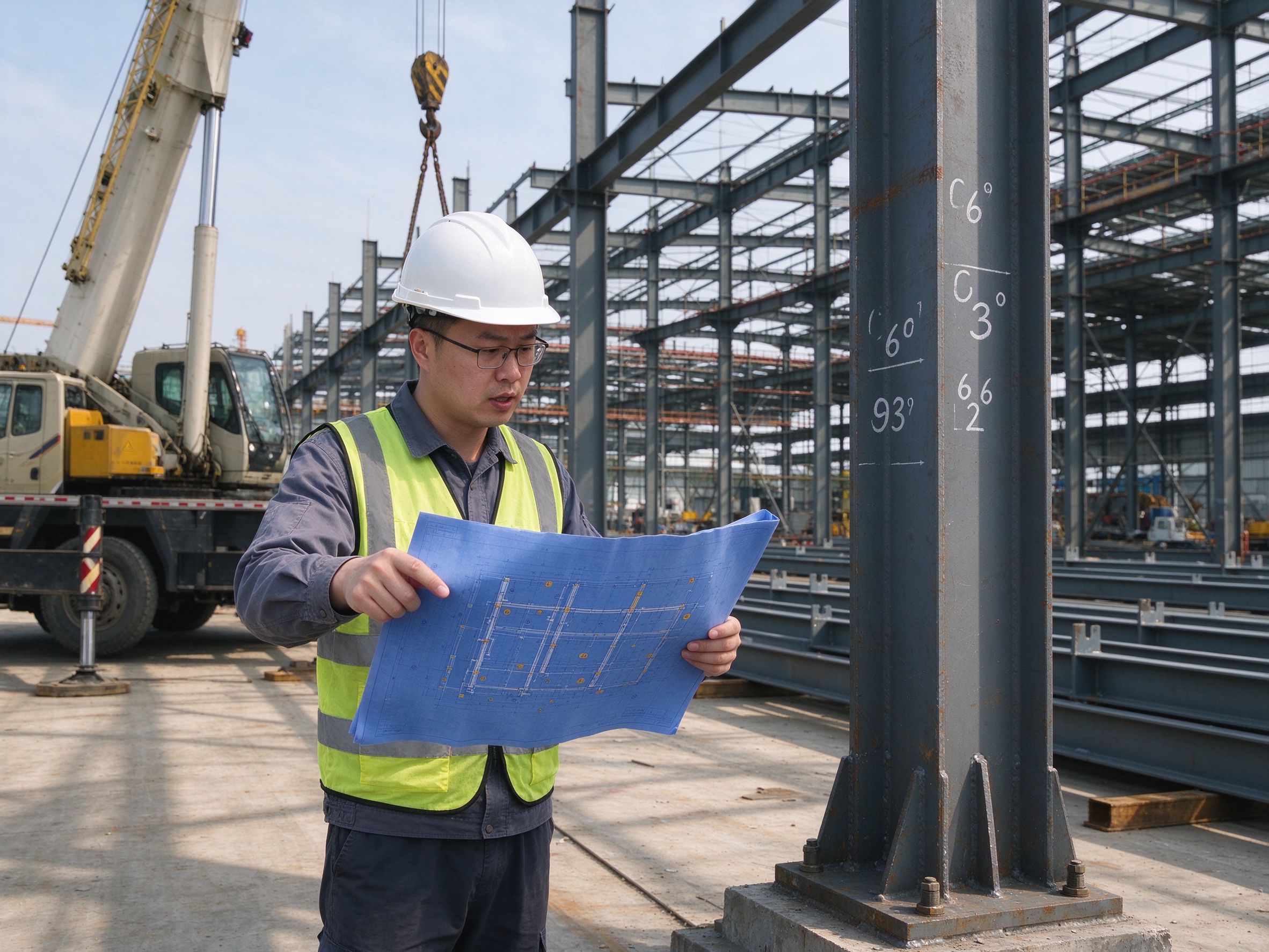
An erection mark (also called member mark, piece mark or assembly mark) is a short alphanumeric code applied to a steel member so that it can be matched to a specific position in the structure. On site, the erection crew reads the mark on the physical member and finds the same mark on the erection drawing, then lifts the member into that position.
Why it matters:
- Speed — a well-marked structure lets the crew find and lift members without re-measuring or guessing.
- Accuracy — members placed in the wrong position can overload connections or delay the whole frame.
- Safety — lifting the wrong, heavier member with the wrong rig can be dangerous.
- Cost — searching, re-handling and re-cutting on site are expensive and delay the programme.
The marking system is usually agreed between the fabricator and the customer before fabrication, and it must be consistent across shop drawings, erection drawings, the members themselves, and the packing/loading list.
Part 2: How steel members are numbered
There is no single global standard for member numbering; the logic is set per project, but good systems follow the same principles:
| Element | What the mark typically shows | Example |
|---|---|---|
| Part type | Letter or code for the component (column, rafter, purlin, brace, tie, girt, etc.) | C = column, R = rafter, P = purlin |
| Sequence number | Number within the type, usually by grid line or bay | C1, C2, C3… |
| Mirror / side indicator | Left/right, hand, or orientation where a member is not symmetrical | C1L / C1R, or a suffix |
| Level / storey (if needed) | Height or storey for multi-level frames | C1-2 (column, grid 1, level 2) |
The mark on the member must be the same mark shown on:
- the shop drawing (fabrication drawing) for that member,
- the erection drawing (layout drawing) showing where it goes,
- the packing list and the mark painted on the packing/lifting position.
Mirror members are a common source of confusion. When a structure is symmetrical, two members can look identical but be manufactured as mirror images. Without an explicit L/R or hand indicator, the site team can lift a member, find it “does not fit”, and only then discover it is the mirror of the required piece.
Part 3: Marking methods compared
| Method | How it works | Durability | Suitable for | Limitations |
|---|---|---|---|---|
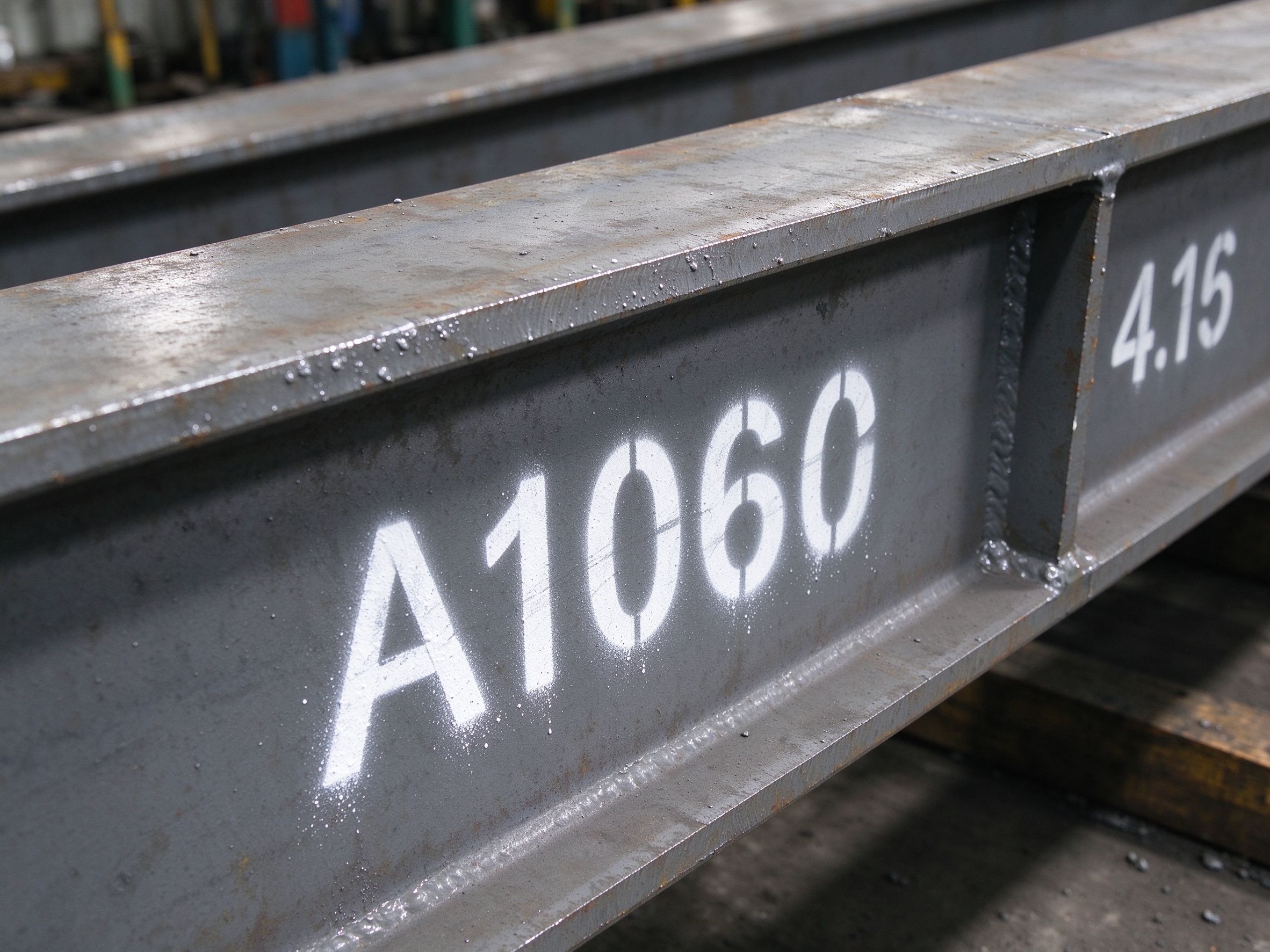
| Paint stencil | Paint sprayed or brushed through a stencil | Good, but can fade or be covered by later coating | Most structural members | Needs clean surface; may need re-marking after painting |
| Metal tag / plate | Attached tag with stamped or engraved mark | Very durable | Members stored outdoors, heavy sections | Can be knocked off; adds cost and time |
| Marker pen | Hand-written mark | Poor | Temporary identification, small jobs | Fades quickly; not reliable outdoors |
| Sticker / label | Adhesive label | Poor in weather | Interim marking, container loading reference | Detaches in rain or heat |
| Bar code / QR (optional) | Printed code readable by scanner | Depends on application | Digital tracking, packing verification | Needs scanner and software on site |
In export projects, the practical choice is usually paint stencils for the main marks (visible and durable enough for site erection) plus a packing mark that tells the site team which container and which lift sequence the member belongs to. The exact method should be confirmed in the contract, together with who re-marks members after surface treatment and after erection damage.
Part 4: Erection drawings vs shop drawings
Buyers often confuse the two. They serve different purposes and carry different marks:
| Aspect | Shop drawing (fabrication drawing) | Erection drawing (layout/erection drawing) |
|---|---|---|
| Purpose | Shows how to fabricate one member | Shows where each member goes in the structure |
| Level of detail | Full dimensions, welds, holes, plate details, material | Member marks, grid lines, levels, connection overview, erection sequence |
| Typical mark | Unique fabrication/member mark per piece | The same member mark, placed at its position |
| User | Fabricator, QC, detailer | Site engineer, erection crew, crane planner |
| Deliverable from | Steel supplier’s detailing (usually) | Steel supplier’s detailing; sometimes the local engineer coordinates |
Both must use the same member marks. If the shop drawing calls a member “C3” but the erection drawing calls it “C2”, the site team will stop and ask — and a full container may have been loaded by then.
Part 5: How marking ties to packing, container loading and erection
For export projects, marking is not only about site erection; it is the link between fabrication, packing, container loading and the erection sequence:
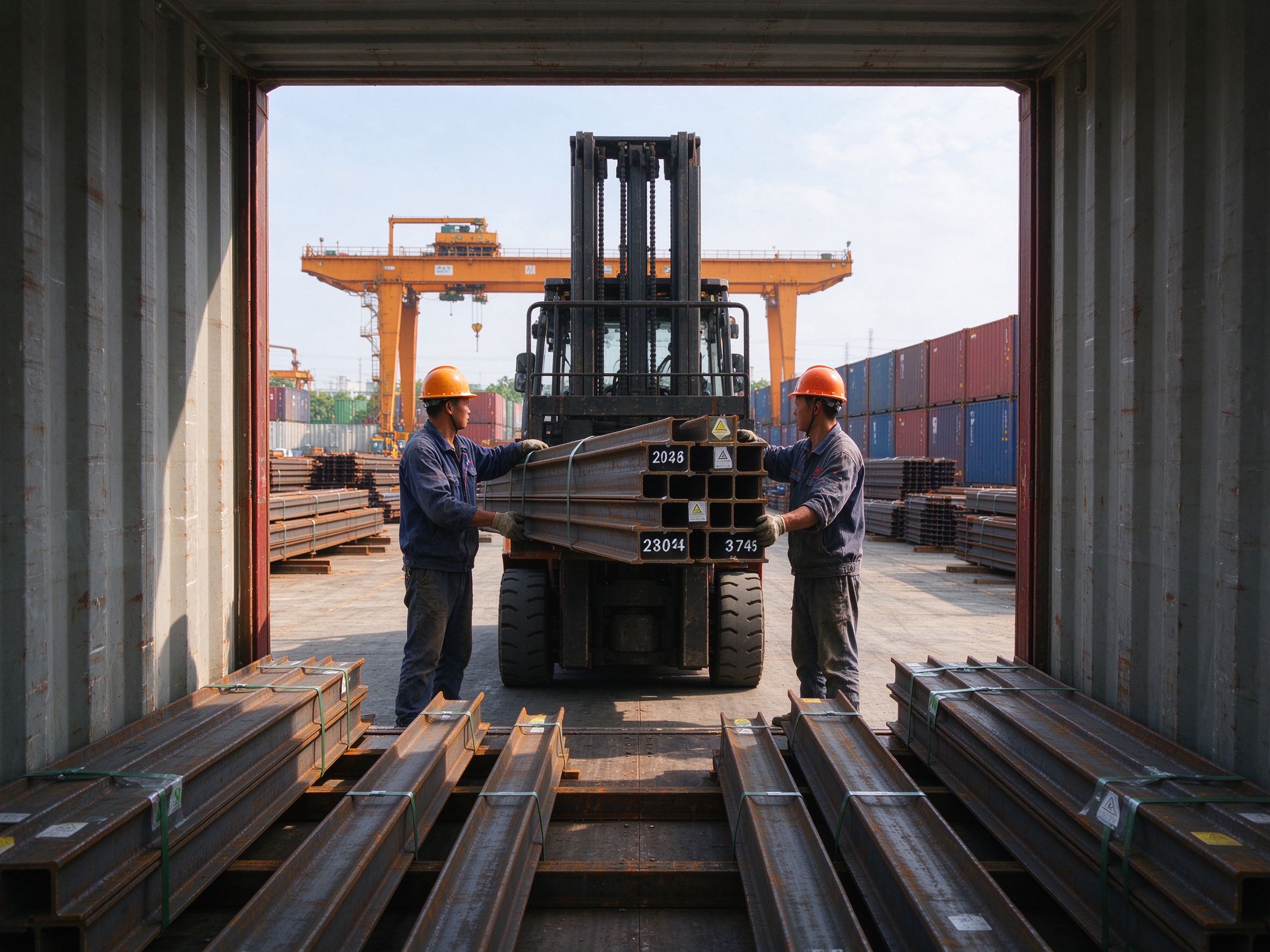
- Packing list groups members by container and by mark. The site team knows which container holds the first bay of the frame.
- Loading sequence should follow the erection sequence. Members needed first are loaded last (so they are unloaded first), and the marks on the members let the loader place them in the correct groups.
- Packing marks are painted on the outside of bundles and on the container manifest. The site team can confirm the correct container without opening everything.
- Fragile and heavy items (bolts, fittings, cladding) are separated by mark and by packing location, so unloading does not damage them.
- The marks on the members and the marks on the packing must match the erection drawings. A mismatch discovered on site usually means manual searching through several containers.
ZhongSai’s manufacturing bases coordinate marking, packing and container loading as part of the steel supply, so the marks on the members match the packing list and the erection sequence. The local team still verifies the marks against the approved erection drawings when receiving the shipment.
Part 6: Common marking mistakes and how to avoid them
- Mirror members not marked — always add an explicit L/R or hand indicator.
- Marking covered by paint or coating — agree whether marking happens before or after surface treatment, and who re-marks after painting.
- Marks not matching between shop and erection drawings — one numbering source must be controlled by the detailer and frozen before fabrication.
- Too-small or low-contrast marks — marks must be readable from a crane operator’s distance and after a long sea voyage.
- No packing-level marks — bundles and containers must carry their own marks so unloading can follow the erection sequence.
- Changes after fabrication — if a member is modified, its mark and drawings must be updated together, or the site will be given obsolete information.
Buyer checklist before shipment:
- Confirm the numbering logic (part type + sequence + mirror indicator) in writing before fabrication.
- Verify that shop drawings and erection drawings use the same member marks.
- Confirm the marking method and who re-marks after surface treatment.
- Ask for a packing list that groups members by container and by erection sequence.
- Check that container and bundle marks are visible and match the packing list.
- Keep one controlled set of drawings at the fabricator and one at the site, both frozen to the same revision.
Part 7: Responsibility boundary — supplier vs local team
| Stage | ZhongSai (steel supplier) | Local team |
|---|---|---|
| Numbering system | Proposes and coordinates the marking logic with the customer; details members and controls the mark list | Approves the marking logic; provides grid/level information |
| Fabrication | Fabricates, marks members (as agreed), matches shop drawings | — |
| Packing & loading | Packs by mark and erection sequence; paints bundle/container marks; issues packing list and manifest | Verifies marks against approved erection drawings at receipt |
| Site erection | Provides installation technical guidance; supports mark interpretation | Erects members by marks and erection drawings; manages local labour, permits and authority submissions |
| Corrections | Updates drawings and marks if fabrication changes | Reports any mismatch promptly with photos |
FAQ
What does an erection mark on a steel beam mean?
It is the member’s identification code, matching the same mark on the erection drawing. It tells the site team which beam this is and where it goes, so the member can be lifted into the correct position without measuring or guessing.
How are steel members numbered?
Typically by part type (letter), sequence number within that type, and a mirror/side indicator where needed. The logic is set per project and must be consistent across shop drawings, erection drawings, packing list and the members themselves.
What is the difference between a shop drawing and an erection drawing?
A shop drawing shows how to fabricate one member (full dimensions, welds, holes); an erection drawing shows where each member goes in the structure (member marks, grid lines, levels). Both must carry the same member marks.
Does ZhongSai mark the members at its manufacturing bases?
Yes — marking, packing and container loading are part of the steel supply scope. Members are marked to match the approved shop and erection drawings, and bundles/containers carry packing marks so unloading can follow the erection sequence. Confirm the exact marking method in your contract.
What happens if a member arrives without a readable mark?
The site should photograph it and check the packing list and erection drawings before cutting or forcing it into place. A missing or faded mark is usually re-identified from the packing list or the fabricator’s record; never re-mark a member by guesswork.
Who decides the numbering system?
The fabricator proposes the logic and coordinates it with the customer’s engineer; the customer approves it before fabrication. Grid lines, levels and building orientation must be agreed first, because they define the reference for every mark.
Why are mirror members so often mixed up on site?
Mirror members look identical but are manufactured as mirror images. If they are not explicitly marked left/right or handed, the crew can lift the wrong member and discover the problem only during fitting. An explicit suffix (L/R) prevents this.
Can members be re-identified after unloading if the container is mixed?
Yes, but it costs time: the crew matches the member’s cross-section and dimensions against the packing list and shop drawings. Good packing discipline (members grouped by mark and by erection sequence) makes re-identification fast.
Ready to coordinate member marking on your steel project?
Send your project drawings and requirements, including grid lines and erection sequence, and ZhongSai will confirm the numbering logic, marking method and packing plan that match your site team’s needs.